
And 2 meters is not the most easy way to start. Why you think you fail, because you get harmonics ? If so, why you think they invented filters. 4v pk-pk modulation showing no carrier to confirm the deviation is as expected. Trace showing Fc-Fo alias, 125MHz Fc, the desired Fc+Fo alias, and I think a spurious at Fc+2Fo.

The worst problem is probably the spurious spikes about 0.8MHz apart seen on the 20MHz span trace, these seem to be mixes of frequency components of data on the SPI bus (the SPI bus was running at 16MHz). It worked more or less as expected but I think it would need some care to get something clean enough to be usable for radio. The PIC ACD input was driven by a function generator. A 910R resistive probe straight on the AD9850 output feeding the SA.
#DSA815 PRACTICE PROJECTS PLUS#
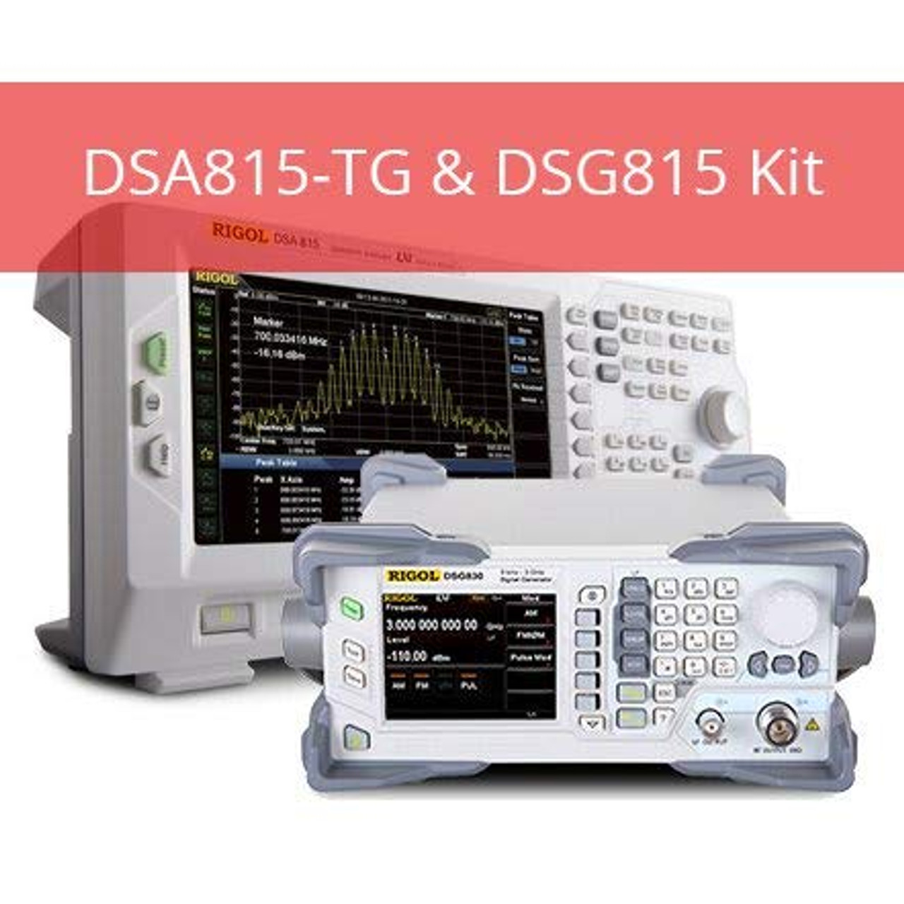
The AD9850 is programmed to generate an Fc+Fo alias at 145.4MHz plus 5kHz deviation for 5v on a PIC ADC input sampled at 16kHz. As shown a PIC24FV32KA301 running at 16 MIPS from its internal oscillator lashed up to a $10 ebay AD9850 board. There are also more specific VHF/UHF books which might be more appropriate for you. The RSGB Handbook isn't cheap, but covers just about everything you're likely to want to know. Look at the RSGB book store where there are loads of different books on RF. I once managed to produce intelligible speech just by shouting at the coil! Lastly, see what other designs people have already done. That is to say, you have an air-cored coil and it will change inductance with sound waves. LC oscillators running at 144 MHz can suffer from microphony. Filter the oscillator output - It's difficult to get the perfect sine wave with absolutely no harmonics, so make the best one you can and then add a bandpass filter to attenuate any remaining harmonics. Buffer the oscillator - Add an additional stage just to 'decouple' the oscillator from what it's driving. Modularise the design - Put each section in it's own screened box, power fed via feed-throughs. Hi Jim, Welcome to the mysteriousness world of RF! I would suggest the following: 1. If anyone is into RF circuitry and could give me some tips, I'd really appreciate it! This is about the best I can do at the moment. EDIT 2: Changed pictures to attachments instead for easier viewing. I was using a BC550C but the current gain is far too high and there are peaks right up to 1.5GHz and probably beyond! Impossible to tame. Trying to source a lower bandwidth transistor so there are less harmonics, but I can live with -52dB from the reference for now. Promise! I recently invested in a Rigol DSA815-TG, so have been using that for my latest oscillator design, as it gives me a better idea of where I am with the circuit compared to my 20MHz oscilloscope and scanner radio! EDIT 1: Oh yeah, I am using a 2N3904 NPN transistor for this oscillator. I've built a few low power radio transmitters in the past and am currently designing a new oscillator that should work in the 2-metre Ham band - I won't use it to broadcast until I get a license. A little about me first: I have been experimenting with very basic RF circuitry for the past year or so and am contemplating whether or not to become a Ham radio operator. My first post on the forum, so I thought I'd share something I'm working on.

#DSA815 PRACTICE PROJECTS SOFTWARE#


 0 kommentar(er)
